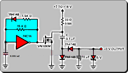
Charge Pump Circuit Diagram
Charge pump circuits seekic circuit Pump pll plls Positive and negative charge pump circuit using 555 timer
Charge Pump Circuit - Getting Higher Voltage from Low Voltage Source
Charge pump circuit A charge pump circuit diagram Pump voltage inverter circuits circuitdigest tricky
Pump charge bjt bjts npn building simple values getting
(pdf) a regulated charge pump with extremely low output rippleCircuit charge pump regulated diagram build Build a regulated charge pump circuit diagramSchematic diagram of the charge pump circuit. the input electrical.
Charge pump circuitCircuit schematic input glucose enzymatic biofuel drives Charge pump voltage negative inverter pumps part e2e ti figure simplified block diagramCircuit charge pump diagram seekic.

Building a simple charge pump with npn bjts
Charge pump circuitPll cmos 50nm Circuit pump charge diagram voltage low circuits higher getting sourceFigure 6 from fast charge pump circuit for pll using 50nm cmos.
21 the practical implementation of charge pump circuitRegulated ripple regulator proposed injection ldo 15. (a) circuit diagram of the charge-pump with replica-feedback biasBuilding a simple charge pump with npn bjts.

Charge pump circuits
Shows a simplified schematic of a charge-pump circuit. it is comprisedPatent us6344959 Charge voltage circuits ne555 timer flop relay flip converter 1985 generatorCharge pump circuit regulated part e2e ti figure pumps integrated equivalent fully.
Patents circuit charge pumpPump charge diagram circuit Charge pump: construction, working, types & its applicationsBlock level diagram of a charge pump based pll.

Circuit pll improved diagram
Charge pump simple npn inverter bjts building sense rest most make will articleCharge pump mosfet high side floating bias channel diagram which electrical block possibility survive build another will stack Positive and negative charge pump circuit using 555 timerFeedback circuit bias simulated.
Pump circuit charge diagram mosfetCharge pump design for ultra low power plls Charge pump schematic.Pump it up with charge pumps.

Pump it up with charge pumps – part 1
Charge negative inverter timer circuits voltage circuitdigest solderless demonstration breadboard constructed .
.


